Home > Construction Training Manuals > Construction Mechanic Advanced > Starter Ground Circuit Resistance Test
to the right until the engine is cranked. The voltmeter lead clips must be in good contact with the battery posts and the starter terminal. Now, turn the voltmeter selector switch to the No. 4 VOLT position. Before cranking the engine with the ignition switch ON, connect a jumper from the secondary terminal of the coil to ground to prevent the engine from starting while it is being tested. While cranking the engine, observe the voltmeter reading which should be within the manufacturer's specifications. Unless otherwise specified by the manufacturer, the voltage loss in each of the circuits shown in views A, B, and C should not exceed the value given.
When you test a 6-volt system, the completed circuit shown in view A allows a 0.2 volt loSS and that of view B, allows a 0.3 volt loss. When you test a 12-volt system, the completed circuit shown in view A allows a 0.4 volt loss and that of view B, a 0.3 volt loss, and that of view C, a 0.1 volt loss. If testing a 24- or 32-volt system, refer to the manufacturer's specifications. If the voltmeter reading is more than specified for the type of system being tested, high resistance is indicated in the cables, switches, or connections. Repeat the test with the voltmeter connected to each cable, switch, and connector of the circuit. The maximum readings taken across these parts should not exceed the values listed below.
| 6 - Volt System | 12 - Volt System | |
| Each cable | 0.1 volt | 0.2 volt |
| Each switch | 0.1 volt | 0.1 volt |
| Each connector | 0.0 volt | 0.0 volt |
STARTER GROUND CIRCUIT RESISTANCE TEST
Excessive resistance in the ground circuit of the starting system can cause sluggish cranking action or failure to crank. It can also seriously interfere with the operations of the electrical circuits using the same ground.
To conduct the starter ground circuit resistance test on a 6-, 12-, or 24-volt series system, perform the following:
Connect the VOLTMETER leads of the tester, as shown in figure 4-26, and observe the polarity as you make the connections. Be sure the voltmeter lead clip at the battery contacts the battery post and not the battery cable clamp. Now, turn the voltmeter selector switch to the No. 4 VOLT position. Before cranking the engine with the ignition switch ON, connect a jumper lead from the secondary terminal of the coil to ground to prevent the engine from starting while it is being tested. While cranking the engine, observe the voltmeter reading. Unless otherwise specified by the manufacturer's
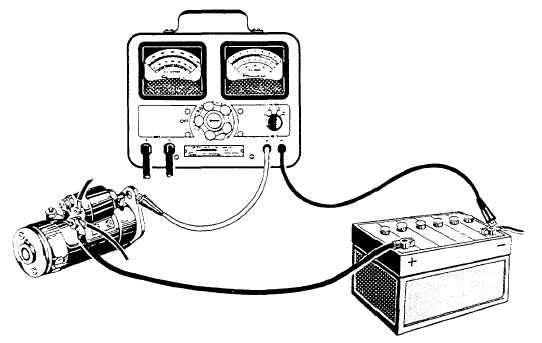
Figure 4-26.-Starter ground circuit resistance test.
Continue Reading