Home > Construction Training Manuals > Utilitiesman (Advanced) > Table 7-6.Minimum Slope For Sewer Pipe
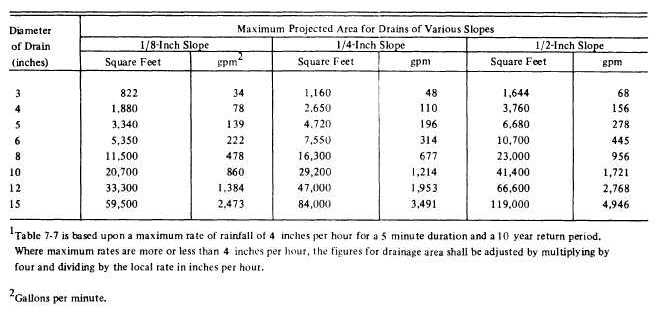
size of pipe to select. One example is table 7-7; it shows storm drain sizes. Remember that this table is to be used only as a guide when estimating for storm drainage, as different areas have different intensities of rainstorms.
Another method for sizing building storm drains is to provide 1 square inch of pipe cross- sectional area for each 100 square feet of roof area. This method is easy to remember: 1 square inch for 100 square feet. (However, it is not as accurate as using table 7-7.) Using this method, you can prepare a table similar to table 7-8. Show the diameter in the first column; then the radius (which is one-half the diameter); then the square of the radius; then the cross-sectional area, which is pi (3.14) times the radius squared. Since each square inch may take 100 square feet of roof, move the decimal of the square inches over two places to the left (which is multiplying by 100) to get the area of the roof that may be drained to the pipe. As you can see by comparing table 7-7 with table 7-8, the second method is much more conservative.
Sizing Site Storm Sewers
While rules of thumb such as those just described are used to size building storm drains, different procedures are used to size the storm sewers that carry the runoff from the building site and surrounding land areas. The design and sizing of storm drains are provided by engineers. It is not necessary that the UT understand the factors that contribute to the design. Therefore, the information is not included here.
WATER SUPPLY SYSTEMS
After the pipe runs and fittings are located on a print or drawing, the size, quantity, and joining requirements of the pipe must be determined. When a plumbing print is available for the job, it will contain this information. If there is no blueprint, you must determine these requirements yourself. The quantity of pipe required and the number and types of fittings you intend to use
Table 7-8.-Fixture Demand
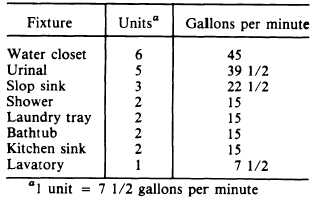
Table 7-7.-Size of Horizontal Building Storm Drains and Building Storm Sewers