Figure 3-65. - Correct valve-to-seat contact after narrowing.
When wear is indicated inside the rocker bore, you can measure it with a telescoping gauge and a micrometer or a bore gauge. Rocker arms with bushings can be rebushed if the old bushing is worn On some rocker arms, worn valve ends can be ground down on the valve grinding machine. Excessively worn rocker arms should be replaced.
Also, inspect the rocker arm shaft for wear. A worn rocker arm shaft has indentions where the rocker arms swivel on the shaft. Wear on the shaft is usually greater on the bottom. Using a micrometer, check the shaft to determine whether wear is within the manufacturer's specifications.
When reinstalling rocker arms and shafts in the cylinder head, make sure that the oil holes (in the shaft if so equipped) are on the underside, so they can feed oil to the rocker arms. Ensure that all spring and rocker arms are restored to their original positions as you attach the shafts to the head.
Valve Spring Service
After prolonged use, valve springs tend to weaken, lose tension, or even break. During engine service, always test valve springs to make sure they are usable. Valve springs should be tested for uniformity and strength. The three characteristics to check are valve spring squareness, valve spring free height, and valve spring tension.
Valve spring squareness
is easily checked with a combination square. Place each spring next to the square on a flat surface. Rotate the spring while checking for a gap between the side of the spring and the square. Replace any spring that is not square.
Valve spring free height
can also be measured with a combination square or a valve spring tester. Simply measure the length of each spring in normal uncompressed condition. If it is too long or too short, replace the spring.
Valve spring tension,
or pressure, is measured by using a spring tester. Compress the spring to specification height and read the scale on the tester. Spring pressure must be within specifications. If the reading is too low, the spring has weakened and must be replaced.
TIMING GEARS (GEAR TRAINS)
Because the crankshaft must rotate twice as fast as the camshaft, the drive member on the crankshaft must be exactly one half as large as the driven member on the camshaft So for the camshaft and crankshaft to work together, they must be in time with each other. This initial position between the two shafts is designated by marks that are called timing marks. To obtain the correct initial relationship of the components, align the corresponding marks at the time of assembly. Timing gears keep the crankshaft and the camshaft turning in proper relation to one another, so the valves open and close at the proper time. This is accomplished by gear- drive, chain-drive, or belt-drive gear trains (fig. 3-66).
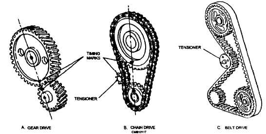
Figure 3-66. - Timing gear trains.
Continue Reading