
Figure 1-7. - Orthographic and isometric drawings.
Once you understand the drawing in figure 1-7, the same idea can be applied to the drawing of the shape of a room, as shown in figures 1-8 and 1-9.
DRAWING AN ISOMETRIC VIEW
To determine the pipe layout, you can draw the dimensions of a room in several ways. Some Engineering Aids suggest that the lines of the room be drawn with fine, light lines, and the pipe diagram with heavy, dark lines to give the effect of a transparent room you can see into, as shown in figure 1-10. This method requires drafting room equipment and is difficult in field sketching.
Another means of visualizing the pipe layout is to "section" or remove from the drawing those parts in front of what is important to show. The usual section in

Figure 1-8. - Isometric drawing of a room.
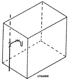
Figure 1-9. - Isometric drawing of a room and drainage pipe.
a plumbing pipe layout leaves the ceiling and two walls out of the drawing, as shown in view C of figure 1-10.
A third method is simpler in that the room is shown only as a partial floor plan view, as shown in view D, figure 1-10. The walls are omitted from the drawing entirely. It is understood that the walls are to be there, but they are left out so the piping diagram is' shown without unnecessary details.
To lay out a 45-degree angle in an isometric drawing, draw a square and lay out the 45-degree angle, as shown in view A, figure 1-11. Now look at view B and you will see a block with a 45-degree chamfer. The chamfer is located by measuring equal distances from the corner that would ordinarily be there.
Continue Reading