allowed to run free to the point where they will destroy themselves.
SIX WINDINGS, SERIES-PARALLEL - Three pairs of series-wound field coils provide the magnetic field for a heavy-duty starter motor. This configuration uses six brushes.
THREE WINDINGS, TWO SERIES, ONE SHUNT - The use of one filled coil that is shunted to ground with a series-wound motor controls motor speed. Because the shunt coil is not affected by speed, it will draw a steady heavy current, effectively limiting speed.
DRIVE END FRAME. - The drive end frame is designed to protect the drive pinion from damage and to support the armature shaft. The drive end frame of the starter contains a bushing to prevent wear between the armature shaft and drive end frame.
Types of Starting Motors
There are two types of starting motors that you will encounter on equipment. These are the direct drive starter and the double reduction starter. All starters require the use of gear reduction to provide the mechanical advantage required to turn the engine flywheel and crankshaft.
DIRECT DRIVE STARTERS. - Direct drive starters make use of a pinion gear on the armature shaft of the starting motor. This gear meshes with teeth on the ring gear. There are between 10 to 16 teeth on the ring gear for every one on the pinion gear. Therefore, the starting motor revolves 10 to 16 times for every revolution of the ring gear. In operation, the starting motor armature revolves at a rate of 2,000 to 3,000 revolutions per minute, thus turning the engine crankshaft at speeds up to 200 revolutions per minute.
DOUBLE REDUCTION STARTER. - The double reduction starter makes use of gear reduction within the starter and the reduction between the drive pinion and the ring gear. The gear reduction drive head is used on heavy-duty equipment.
Figure 2-42 shows a typical gear reduction starter. The gear on the armature shaft does not mesh directly with the teeth on the ring gear, but with an intermediate gear which drives the driving pinion. This action provides additional breakaway, or starting torque, and greater cranking power. The armature of a starting motor with a gear reduction drive head may rotate as many as 40 revolutions for every revolution of the engine flywheel.
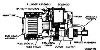
Figure 2-42. - Gear reduction starter.
NEUTRAL SAFETY SWITCH
Vehicles equipped with automatic transmissions require the use of a neutral safety switch.
The neutral safety switch prevents the engine from being started unless the shift selector of the transmission is in NEUTRAL or PARK. It disables the starting circuit when the transmission is in gear. This safety feature prevents the accidental starting of a vehicle in gear, which can result in personal injury and vehicle damage. The neutral safety switch is wired into the circuit going to the starter solenoid. When the transmission is in forward or reverse gear, the switch is in the OPEN position (disconnected). This action prevents current from activating the solenoid and starter when the ignition switch is turned to the START position. When the transmission is in neutral or park, the switch is closed (connected), allowing current to flow to the starter when the ignition is turned.
A misadjusted or bad neutral safety switch can keep the engine from cranking. If the vehicle does not start, you should check the action of the neutral safety switch by moving the shift lever into various positions while trying to start the vehicle. If the starter begins to work, the switch needs to be readjusted.
To readjust a neutral safety switch, loosen the fasteners that hold the switch. With the switch loosened, place the shift lever into park (P). Then, while holding the ignition switch in the START position, slide the neutral switch on its mount until the engine cranks. Without moving the switch, tighten the fasteners. The engine should now start with the shift lever in park or neutral. Check for proper operation after the adjustment.
If by adjusting the switch to normal operation is not resumed, it may be required to test the switch. All that is required to test the switch is a 12-volt test light.
Continue Reading