relationship of parts. Electrical diagrams are usually used to show how the parts of a piece of equipment or several pieces of equipment are wired together. These diagrams are similar to each other. Their names are sometimes used interchangeably, but they do have differences.
The types of diagrams with which you will be working are covered below. The short description of each should enable you to recognize the different diagrams.
ISOMETRIC WIRING DIAGRAMS
The isometric wiring diagram is not used very often in electrical work. When used, it shows the electrical relationship in multilevel buildings, between floors, or the total electrical system. In the isometric diagram, the cable and fixtures are shown only in their general location. Their exact locations are given in the electrical prints. (See fig. 4-4.)
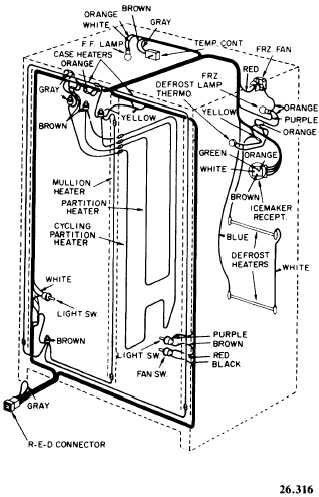
Figure 4-4. - Schematic wiring diagram of side-by-side refrigerator with automatic ice maker.

Figure 4-5. - Block diagram.
A block diagram is a simple drawing showing the relationship of major parts of a system. Figure 4-5 shows a block diagram of a motor control system. You can easily see why it is called a block diagram. The parts or components in any block diagram will be shown just as they appear in this drawing, as blocks. They are then connected by a line or lines that show the relationship of the parts. The internal connections of the components are not shown in these drawings. The blocks are simply labeled to show what each represents. These drawings would be of little help for troubleshooting.
WIRING DIAGRAMS
The wiring diagram, which is like a picture drawing, shows the wiring between components and the relative position of the components.
Continue Reading