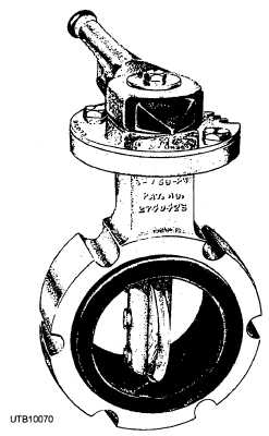
Figure 4-4. - Butterfly valve.
The butterfly valve shown in figure 4-4 consists of a body, a resilient seat, a butterfly type of disk, a stem, packing, and a notched positioning plate and handle. The resilient seat is under compression when it is mounted in the valve body. The compression causes a seal to form around the edge of the disk and both upper and lower points where the stem passes through the seat. Packing is provided to form a positive seal around the stem if the seal formed by the seat is damaged.
To close the valve, turn the handle a quarter of a turn to rotate the disk 90 degrees. The resilient seat exerts positive pressure against the disk, which assures a tight shutoff. The larger size butterfly valves have electrical or mechanical gear-driven mechanisms to open or close the valve.
Butterfly valves are easy to maintain. The resilient seat is held in place by mechanical means; therefore, neither bonding nor cementing is necessary. Since the resilient seat is replaceable, the valve seat does not require any lapping, grinding, or machine work.
Butterfly valves serve a variety of requirements. These valves are now being used in salt water, fresh water, JP-5 fuel, naval distillate fuel oil, diesel oil, lubricating oil systems, and air ventilation systems.
CHECK VALVE
Check valves permit liquids to flow through a line in one direction only; for example, they are used in drain lines where it is important that there is no backflow. Considerable care must be taken to see that valves are installed properly. Most of them have an arrow, or the word inlet, cast on the valve body to indicate direction of flow. If not, you must check closely to make sure the flow of the liquid in the system operates the valve in the proper manner.
The port in a check valve may be closed by a disk, a ball, or a plunger. The valve opens automatically when the pressure on the inlet side is greater than that on the outlet side. They are made with threaded, flanged, or union faces, with screwed or bolted caps, and for specific pressure ranges.
The disk of a SWING-CHECK valve (fig. 4-5) is raised as soon as the pressure in the line below the disk is of sufficient force. While the disk is raised, continuous flow takes place. If for any reason the flow is reversed or if back pressure builds up, this opposing pressure forces the disk to seat, which, in turn, stops the flow. Swing-check valves are used in horizontal lines and have a small amount of resistance to flow.
The operation of a LIFT-CHECK valve (fig. 4-6) is basically the same as that of the swing-check valve. The difference is the valve disk moves in an up-and- down direction instead of through an arc. Lift-check valves are used in lines where reversal of flow and pressures are changing frequently. This valve does not chatter or slam as the swing-check valve does, but it does cause some restriction of flow.
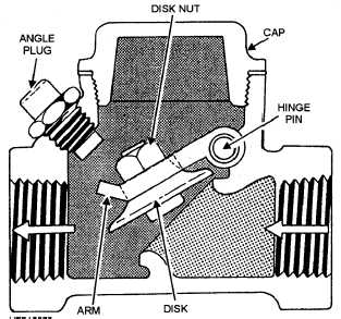
Figure 4-5. - Swing-check valve.
Continue Reading