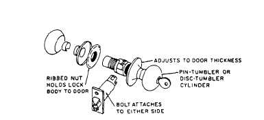
Figure 6-30.—Parts of a cylinder lock.
The door should now be placed in the opening and
blocked up at the bottom for proper clearance. The jamb
should be marked at the hinge locations, and the
remaining hinge half routed and fastened in place. The
door should then be positioned in the opening and the
pins slipped in place. If you have installed the hinges
correctly and the jambs are plumb, the door should
swing freely.
Locks
The types of door locks differ with regard to
installation, cost, and the amount of labor required to set
them. Some types, such as mortise locks, combination
dead bolts, and latch locksets, require drilling of the
edge and face of the door and then routing of the edge
to accommodate the lockset and faceplate (fig, 6-29,
view B). A bored lockset (view C) is easy to install since
it requires only one hole drilled in the edge and one in
the face of the door. Boring jigs and faceplate markers
are available to ensure accurate installation.
The lock should be installed so that the doorknob is
36 to 38 inches above the floor line. Most sets come with
paper templates, marking the location of the lock and
size of the holes to be drilled. Be sure to read the
manufacturer’s installation instructions carefully.
Recheck your layout measurements before you drill any
holes.
The parts of an ordinary cylinder lock for a door are
shown in figure 6-30. The procedure for installing a lock
of this type is as follows:
1.
2.
3.
Open the door to a convenient working position
and check it in place with wedges under the
bottom near the outer edge.
Measure up 36 inches from the floor (the usual
knob height), and square a line across the face
and edge of the lock stile.
Place the template, which is usually supplied
with a cylinder lock, on the face of the door at
the proper height and alignment with layout
lines and mark the centers of the holes to be
drilled. (A typical template is shown in fig.
6-31.)
Figure 6-31.—Drill template for locksets.
6-20