Home > Construction Training Manuals > Construction Electrician Intermediate > Mechanical And Fusion Splices
installed cable plant, the OTDR can characterize optical fiber and optical connection properties along the entire length of the cable plant. A fiber-optic cable plant consists of optical fiber cables, connectors, splices, mounting panels, jumper cables, and other passive components. A cable plant does not include active components, such as optical transmitters or receivers.
The OTDR displays the backscattered and reflected optical signal as a function of length. The OTDR plots half the power in decibels (dB) versus half the distance. Plotting half the power in dB and half the distance corrects for round-trip effects. By analyzing the OTDR plot, or trace, you can measure fiber attenuation and transmission loss between any two points along the cable plant. You also can measure insertion loss and reflectance of any optical connection. In addition, you use the OTDR trace to locate fiber breaks or faults. Figure 6-4 shows an example OTDR trace of an installed cable plant.
MECHANICAL AND FUSION SPLICES
Mechanical splicing involves using mechanical fixtures to align and connect optical fibers. Mechanical splicing methods may involve either passive or active core alignment. Active core alignment produces a lower loss splice than passive alignment; however, passive core alignment methods can produce mechanical splices with acceptable loss measurements even with single mode fibers.
In the strictest sense, a mechanical splice is a permanent connection made between two optical fibers. Mechanical splices hold the two optical fibers in alignment for an indefinite period of time without movement. The amount of splice loss is stable over time and unaffected by changes in environmental or mechanical conditions.
The types of mechanical splices that exist for mechanical splicing include glass, plastic, metal, and ceramic tubes; also included are V-groove, and rotary devices: Materials that assist mechanical splices in splicing fibers include transparent adhesives and index matching gels.
Transparent adhesives are epoxy resins that seal mechanical splices and provide index matching between the connected fibers.
GLASS OR CERAMIC ALIGNMENT TUBE SPLICES
Mechanical splicing may involve the use of a glass or ceramic alignment tube or capillary. The inner diameter of this glass or ceramic tube is only slightly larger than the outer diameter of the fiber. A transparent adhesive, injected into the tube, bonds the two fibers together. The adhesive also provides index matching between the optical fibers. Figure 6-5 illustrates fiber alignment using a glass or ceramic tube. This splicing technique relies on the inner
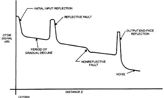
Figure 6-4. - OTDR trace of an installed cable plant.
Continue Reading