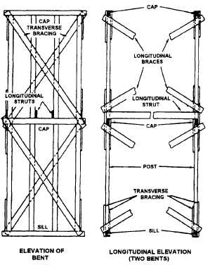
bracing. Figure 10-3 shows both types for a
two-story trestle bent.
Cap— The uppermost transverse horizontal
structural member of a bent. It is laid across the tops
of the posts.
Decking— The structure laid on the girders to form
the roadway across the trestle, It consists of a lower
layer of timbers (flooring) and an upper layer of
timbers (treadway).
Footing— The supports placed under the sills. In
an all-timber trestle, the footings consist of a series
of short lengths of plank. Whenever possible,
however, the footings are made of concrete,
Girder— One of a series of longitudinal supports
for the deck, which is laid on the caps. Also called
a stringer,
Post— One of the vertical structural members.
Sill— The bottom transverse horizontal structural
member of a trestle bent, on which the posts are
anchored, or transverse horizontal member, which
supports the ends of the girders at an abutment.
Substructure— The supporting structure of braced
trestle bents, as distinguished from the super-
structure.
Superstructure— The spanning structure of
girders and decking, as distinguished from the
substructure.
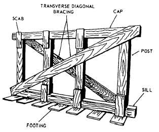
Trestle Bent— A single-story bent or a multistory
bent and the support framework or substructure of
a trestle. The parts of a single-story bent are shown
in figure 10-4. A two-story bent is shown above in
figure 10-3.
CONSTRUCTION
After the center line of a trestle has been deter-
mined, the next step is to locate the abutment on each
bank at the desired or prescribed elevation. The abut-
ments are then excavated to a depth equal to the com-
bined depths of the decking and the stringers, less an
allowance for settlement. The abutment footings and
the abutment sills are then cut, placed, and leveled (as
in fig, 10-2).
The horizontal distance from an abutment sill to the
first bent and from one bent to the next is controlled by
the length of the girder stock. It is usually equal to the
length of the stock, minus about 2 feet for overlap.
Girder stock is usually in 14-foot lengths. The center-
to-center horizontal distance between bents is usually
14 minus 2, or 12 feet.
To determine the locations of the seats for the trestle
bents and the heights of the bents (fig. 10-5), first stretch
a tape from the abutment along the center line. Use a
builder’s level or a line level to level the tape. Drop a
plumb bob from the 12-foot mark on the tape to the
ground. The position of the plumb bob on the ground
will be the location of the first bent. The vertical dis-
tance from the location of the bob to the horizontal tape,
Figure 10-3.-Two–story trestle bent.
10-2
Figure 10-4.-Components of a single-story trestle bent.