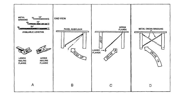
Figure 1-27.—Metal cross bridging.
tops of the bridging. Instep 3, reverse direction and nail
tops of the opposite pieces into place.
Another approved system of cross bridging uses
metal pieces instead of wood and requires no nails. The
pieces are available for 12-, 16-, and 24-inch joist
spacing (fig. 1-27, view A). You can see how to install
this type of cross bridging in views B, C, and D. In view
B, strike the flat end of the lower flange, driving the
flange close to the top of the joist. In view C, push the
lower end of the bridging against the opposite joist. In
view D, drive the lower flange into the joist.
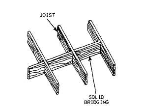
SOLID BRIDGING.— Also known as solid
blocking, solid bridging (fig. 1-28) serves the same
purpose as cross bridging. This method is preferred by
many Builders to cross bridging. The pieces are cut from
lumber the same width as the joist material. They can be
installed in a straight line by toenailing or staggering. If
staggered the blocks can be nailed from both ends,
resulting in a faster nailing operation. Straight lines of
blocking may be required every 4 feet OC to provide a
nailing base for a plywood subfloor.
Placing Floor Joists
Before floor joists are placed, the sill plates and
girders must be marked to show where the joists are to
Figure 1-28.—Solid bridging.
be nailed. As we mentioned earlier, floor joists are
usually placed 16 inches OC.
For joists resting directly on foundation walls,
layout marks may be placed on the sill plates or the
header joists. Lines must also be marked on top of the
girders or walls over which the joists lap. If framed walls
are below the floor unit, the joists are laid out on top of
the double plate. The floor layout should also show
where any joists are to be doubled. Double joists are
required where partitions resting on the floor run in the
same direction as the floor joists. Floor openings for
stairwells must also be marked.
1-13