Home > Construction Training Manuals > Utilitiesman (Advanced) > Figure 14-7.An Expendable Spray System.
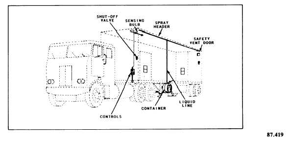
Figure 14-7. - An expendable spray system.
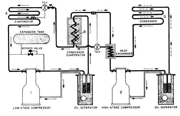
Figure 14-8. - Cascade refrigeration system.
condenser B of system 1 is being cooled by evaporator C of system 2. This arrangement enables ultralow temperatures in evaporator A of system 1. The condenser of system 2 is shown at point D in the figure. Two TEV refrigerant controls are also indicated in the figure. Notice the use of oil separators to minimize the circulation of oil.
Compound System
The compound system uses two or more compressers connected in series in the same refrigeration system. In this type of system the first stage compressor is the largest and for each succeeding stage the compressor gets smaller. This is because
Continue Reading