balancing a column of liquid of known weight against air pressure. The units of measure used are pounds per square inch, inches of mercury using mercury as the fluid, and inches of water using water as the fluid.
The simplest form of manometer is the basic U-tube type. Several variations of the basic type are presently used in air movement applications, for example, the inclined type (draft gauge) and the combination inclined and vertical type. An inclined manometer with a pitot probe is shown in figure 13-10. Many commercially installed central duct systems have permanently mounted manometers connected to duct interiors with static pressure tips.
Rotating Vane Anemometer
The rotating vane anemometer (fig. 13-11) consists of a propeller or revolving vane connected through a gear train to a set of recording dials that indicate the number of linear feet of air passing in a measured length of time. It requires correction factors and frequent calibrations, and it is not as accurate as the velometer.
The primary application for a rotating vane anemometer is the measurement of grille velocities on heating, cooling, and ventilating installations; however, it may not be suitable for exhaust measurements or for measurements on very small grilles.
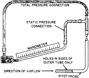
Figure 13-10.-Inclined manometer with pitot probe.
Miscellaneous Instruments
In addition to the air balancing instruments, there are other miscellaneous devices required. Thermometers are necessary for making temperature measurements at various duct and room locations; a tachometer is needed to determine fan speeds; and a multimeter is needed to check fan motors for proper operation.
PREPARATION FOR BALANCING
The following preliminary procedure is necessary before proper balancing can begin. These steps are general in nature and should apply to most situations.
1. Review applicable mechanical drawings and job specifications. This review will provide necessary data on the ducts, air handlers, and outlets. Information pertaining to design airflow can also be taken from these drawings.
2. Prepare a simple working sketch of the entire duct system showing dimensions, airflow volumes and velocities, and the location of all components such as dampers, fans, coils, and filters. Duct outlets should be numbered on the sketch starting at the farthest one from the fan
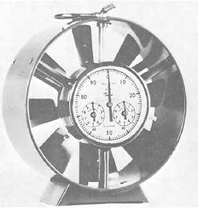
Figure 13-11.-Rotating vane anemometer.
Continue Reading