after about 3 to 4 seconds, the motor reaches its rated speed and the current decreases, causing the relay contact to open and disconnect the winding. Current relays are ideal for use with split-phase, induction-run motors.
Figure 14-35 is a schematic diagram of a current relay motor starting circuit.
Voltage Relay
A voltage relay looks much like a current relay; however, it differs in operation. It operates on increased voltage as the motor reaches rated speed, and, unlike the current relay, the contacts remain closed during the off cycle. When the motor is first turned on, it draws heavy current and the voltage drop across the starting winding is low. As the motor picks up speed, there is less and less load; therefore, more and more voltage is induced into the winding. At about three-fourths rated speed the voltage is high enough to cause the relay coil to pull the contacts open and disconnect the winding. Voltage relays are used with
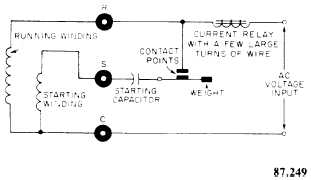
Figure 14-35. - Schematic diagram of a current relay motor starting circuit.
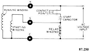
Figure 14-36. - Schematic diagram of a voltage relay motor starting circuit.
capacitor-start motors. Figure 14-36 is a schematic diagram of voltage relay motor starting circuit.
Thermal Relay
A thermal relay is commonly known as a hot-wire relay. It is available in at least two different basic designs and is supplied by several manufacturers. All thermal relays operate on the theory that electrical energy can be turned into heat energy and that, when the temperature of a metal is increased, the metal expands. Thermal relays, like current and voltage relays, operate the starting winding circuit. In addition, the thermal relay controls the running winding circuit, if for any reason the circuit draws excessive current.
The device consists of a specially calibrated wire made from a material with high oxidation resistance and two sets of contacts, all of which are integrally attached to form the relay. Figure 14-37 illustrates a typical thermal relay motor starting circuit. The contacts are controlled by the hot wire, either through the use of heat-absorbing
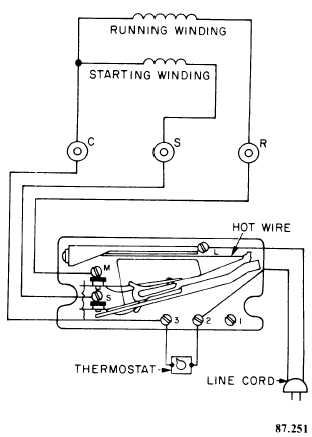
Figure 14-37. - A typical thermal relay motor starting circuit.
Continue Reading