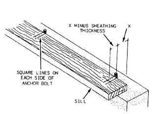
Figure 1-2.—Anchor bolt layout.
length, you should halve the splice joint at least 2 feet
and bolt together.
Once the required length has been determined, the
next step is to lay out the locations of the anchor bolt
holes.
1.
2.
3.
4.
5.
Use the following steps:
Establish the building line points at each of the
corners of the foundation.
Pull a chalk line at these established points and
snap a line for the location of the sill.
Square the ends of the sill stock, (Stock received
at jobsites is not necessarily squared at both
ends.)
Place the sill on edge and mark the locations of
the anchor bolts.
Extend these marks with a square across the
width of the sill. The distance X in figure 1-2
shows how far from the edge of the sill to bore
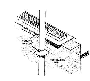
Figure 1-4.—Installing termite shields.
the holes; that is, X equals the thickness of the
exterior sheathing.
After all the holes are marked, bore the holes. Each
should be about 1/4 inch larger than the diameter of the
bolts to allow some adjustment for slight inaccuracies
in the layout. As each section is bored, position that
section over the bolts.
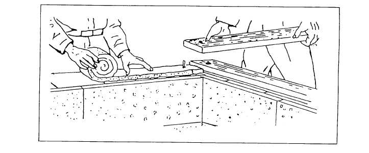
When all sill sections are fitted, remove them from
the anchor bolts. Install sill sealer (insulation) as shown
in figure 1-3. The insulation compresses, filling the
irregularities in the foundation. It also stops drafts and
reduces heat loss. Also install a termite shield (fig. 1-4)
if specified. A termite shield should be at least 26-gauge
aluminum, copper, or galvanized sheet metal. The outer
edges should be slightly bent down. Replace the sills and
Figure 1-3.—Installing sill sealer.
1-2