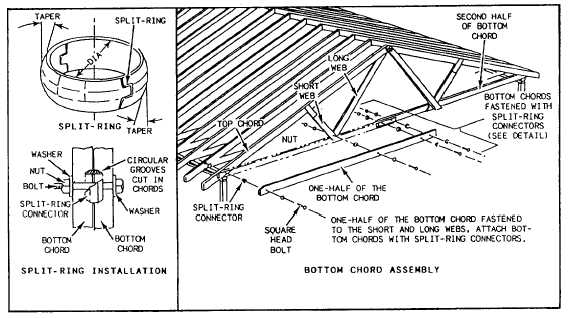
Figure 2-66.-Truss members fastened together with split-ring connectors.
A great majority of the trusses used are fabricated
with plywood gussets (fig. 2-64, views A through E),
nailed, glued, or bolted in place. Metal gusset plates (fig.
2-65) are also used. These are flat pieces usually
manufactured from 20-gauge zinc-coated or galvanized
steel. The holes for the nails are prepunched. Others are
assembled with split-ring connectors (fig. 2-66) that
prevent any movement of the members. Some trusses
are designed with a 2- by 4-inch soffit return at the end
of each upper chord to provide nailing for the soffit of
a wide box cornice.
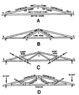
Tension and Compression
Each part of a truss is in a state of either tension or
compression (see fig. 2-67). The parts in a state of
tension are subjected to a pulling-apart force. Those
under compression are subjected to a pushing-together
force. The balance of tension and compression gives the
truss its ability to carry heavy loads and cover wide
spans.
In view A of figure 2-67, the ends of the two top
chords (A-B and A-C) are being pushed together
(compressed). The bottom chord prevents the lower
ends (B and C) of the top chords from pushing out;
therefore, the bottom chord is in a pulling-apart state
(tension). Because the lower ends of the top chords
cannot pull apart, the peak of the truss (A) cannot drop
down.
In view B, the long webs are secured to the peak of
the truss (A) and also fastened to the bottom chord at
points D and E. This gives the bottom chord support
along the outside wall span. The weight of the bottom
chord has a pulling-apart effect (tension) on the long
webs.
In view C, the short webs run from the intermediate
points F and G of the top chord to points D and E of the
bottom chord. Their purpose is to provide support to the
top chord. This exerts a downward, pushing-together
force (compression) on the short web.
Figure 2-67.—Tension and compression in a truss.
2-41