shows a rubble-mound seawall. The stone protecting
the shoreline against erosion is called riprap. There-
fore, a rubble-stone seawall is called a riprap seawall.
Various types of cast-in-place concrete seawalls
are the vertical-face, inclined-face, curved-face,
stepped-face, and combination curved-face and
stepped-face. The sea or harbor bottom along the toe
(bottom of the outside face) of a seawall is usually
protected against erosion (caused by the backpull of
receding waves) by riprap piles against the toe.
Groins
Groins, built like breakwaters or jetties, extend
outward from the shore. Again, they differ mainly in
function. A groin is used where a shoreline is in danger
of erosion caused by a current or wave action running
obliquely against or parallel to the shoreline. It is
placed to arrest the current or wave action or to deflect
it away from the shoreline.
Groins generally consist of tight sheet piling of
creosoted timber, steel, or concrete, braced with wales
and with round piles of considerable length. Groins
are usually built with their tops a few feet above the
sloping beach surface that is to be maintained or
restored.
Bulkheads
A bulkhead has the same general purpose as a
seawall: to establish and maintain a stable shoreline.
But, whereas a seawall is self-contained, relatively
thick, and supported by its own weight, a bulkhead is
a relatively thin wall supported by a series of tie wires
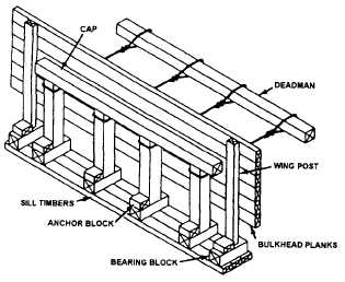
Figure 10-26.-Timber bulkhead for bridge abutment.
or tie rods, running back to a buried anchorage
(deadman). A timber bulkhead for a bridge abutment
is shown in figure 10-26. It is made of wood sheathing
(square-edged, single-layer planks), laid horizontally.
Most bulkheads, however, are made of steel sheet
piles, an example of which is shown in figure 10-27.
The outer ends of the tie rods are anchored to a steel
wale running horizontally along the outer face of the
bulkhead.
This wale is usually made up of pairs of steel
channels bolted together, back to back. A channel is a
structural steel member with a U-shaped section.
Sometimes the wale is placed on the inner face of the
bulkhead, and the piles are bolted to it.
The anchorage shown in figure 10-27 is covered
by backfill. In stable soil above the groundwater level,
the anchorage may consist simply of a buried timber,
a concrete deadman, or a row of driven and buried
sheet piles. A more substantial anchorage for each tie
rod is used below the groundwater level. Two
common types of anchorages are shown in figure
10-28. In view A, the anchorage for each tie rod
consists of a timber cap, supported by a batter pile. In
view B, the anchorage consists of a reinforced
concrete cap, supported by a pair of batter piles. As
indicated in the figure, tie rods are supported by piles
located midway between the anchorage and the
bulkhead.
Bulkheads are constructed from working
drawings like those shown in figure 10-29. The detail
plan for the bulkhead shows that the anchorage
consists of a row of sheet piles to which the inner ends
Figure 10-27.-Constructed steel sheet pile bulkhead.
10-14