structure. Never omit any part called for on the
detailed erection drawings. Each of the members,
parts, and accessories is labeled by stencil; it is not
necessary to guess which part goes where. Refer to the
erection plans and find the particular members you
need as you work.
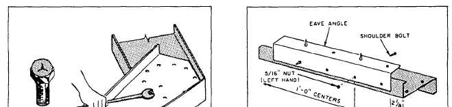
High-strength steel bolts are used at rigid-frame
connections: roof-beam splice and roof beam to
column. These high-strength bolts are identified by a
Y stamped into the head, as shown in figure 9-3. All
high-strength steel bolts and nuts should be tightened
to give at least the required minimum bolt tension
values. The bolts may be tightened with a torque
wrench, an impact wrench, or an open-end wrench.
When a PEB is not erected on a concrete slab, a
floor system by the same manufacturer should be used.
Read and follow the manufacturer’s instructions when
you are installing the floor system.
Layout
After the floor system or concrete slab has been
prepared, the next step is to uncrate and lay out the
structural parts. Lay the parts out in the following
manner:
Parts making up the frame assembly should be
laid out, ready for assembly and in position for
raising.
Girts, purlins, and base angles should be di-
vided (equally) along each side of the founda-
tion.
End-wall parts should be divided equally be-
tween the two ends.
Figure 9-3.—High-strength steel bolt.
All miscellaneous parts should be centrally lo-
cated.
Panels and other parts not used immediately
should be placed on boards and protected from
the environment and jobsite debris.
Lay out the column and roof beams for assem-
bly, using crate lumber to block up the frames.
Erect the center frame first. Use the minimum
number of high-strength bolts to bring the
frame members together. Install the remaining
bobs to get the proper tightness.
Exterior Assembly
Use galvanized machine bolts to assemble the girt
and purlin clips to the frame. Keep in mind that the
end frames have girt and purlin clips on one side only.
The center frame has girt and purlin clips on each side
of the frame.
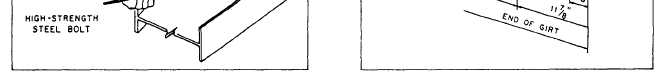
The cave girts should be attached to the cave
angles with 5/16-inch left-hand nuts and shoulder
bolts. An example is shown in figure 9-4. You will
need two cave angles for each cave girt. In fastening
these together, remember the short section of the cave
angle is always fastened to the left side of the cave girt.
The long section of the cave angle is fastened to the
right side of the eave girt.
Use 3/8- by 1-inch galvanized machine bolts to
attach the gable angle and doorjamb top clips to the
bottom flange of the end frame roof beams.
A-FRAME.— To erect the frame, place A-frame
props in position—one 8-foot frame at each side of the
building and a 10-foot frame in the center of the
Figure 9-4.—Attaching eave angle to girt.
9-4