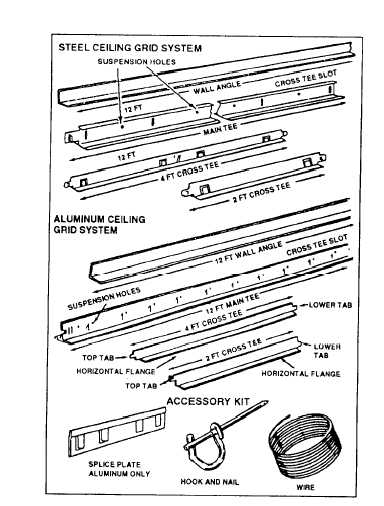
Figure 5-17.—Grid system components.
material requirements. Figure 5-17 shows the major
components of a steel and aluminum ceiling grid system
used for the 2- by 2-foot or 2- by 4-foot grid patterns
shown in figure 5-18.
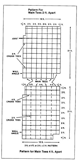
Pattern Layout
The layout of a grid pattern and the material
requirements are based on the ceiling measurements and
the length and width of the room at the new ceiling
height. If the ceiling length or width is not divisible by
2 (that is, 2 feet), increase those dimensions to the next
higher dimension divisible by 2. For example, if a
ceiling measures 13 feet 7 inches by 10 feet 4 inches,
the dimensions should be increased to 14 by 12 feet for
material and layout purposes. Next, draw a layout on
graph paper. Make sure the main tees run perpendicular
to the joists. Position the main tees on your drawing so
the border panels at room edges are equal and as large
as possible. Try several layouts to see which looks best
with the main tees. Draw in cross tees so the border
panels at the room ends are equal and as large as
possible. Try several combinations to determine the
Figure 5-18.—Grid layout for main tees.
best. For 2- by 4-foot patterns, space cross tees 4 feet
apart. For 2- by 2-foot patterns, space cross tees 2 feet
apart. For smaller areas, the 2- by 2-foot pattern is
recommended
Material Requirements
As indicated in figure 5-17, wall angles and main
tees come in 12-foot pieces. Using the perimeter of a
room at suspended ceiling height, you cart determine the
number of pieces of wall angle by dividing the perimeter
by 12 and adding 1 additional piece for any fraction.
Determine the number of 12-foot main tees and 2-foot
or 4-foot cross tees by counting them on the grid pattern
5-16